| TigerJython4Kids | robotics |
Warning: Undefined array key 0 in /var/www/html/engl/navigation.inc.php on line 32
Warning: Trying to access array offset on value of type null in /var/www/html/engl/navigation.inc.php on line 32
Getting started Python Crash Course LED Display Accelerometer Buttons Sound Compass Sensor Bluetooth Moving Robots Alarm Systems Workheets Worksheet 1 Worksheet 2 Worksheet 3 Worksheet 4 Worksheet 5 Appendix: Digital Display Documentation mbRobot and IoT NEW!
| Deutsch English |
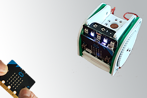
WORKSHEET 2: MOVEmini
![]()
ASSEMBLY AND OPERATION PRINCIPLES |
|
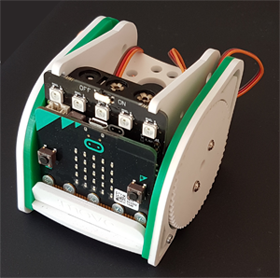
STARTING UP |
from neopixel import *
np = NeoPixel(pin0, 5)
Now you can easily set the RGB color of each pixel individually by selecting the pixel (i = 0..4) like in a list with np[i] and assigning it a tuple of RGB values (3 numbers between 0 and 255). For example, to set the LED with index 1 to a green color: np[1] = (0, 10, 0) However the LED does not light up unless you call: np.show() Write the program and execute it.
Attention: If your pixels are not lit, you probably forgot np.show()!
It is easy to create a PWM signal on P1 (for the right motor) by calling pin1.write_analog(duty_cycle) Here the duty_cycle is given as a number between 0 and 1023 (that correspond to a duty cycle of 0..100%). The motor is rotating faster and faster for values between about 73 and 93. For values between about 73 and 63, it's getting faster and faster, but turns in the opposite direction. |
MOVING FORWARD AND TURN |
To drive forward, both wheels must rotate at the same speed. Because the motors are arranged opposite, their rotation have to be opposite for a forward move. However because of inaccuracies you cannot achieve a straight forward movement. Adjust the number 72 so that this is almost the case. To turn left, you stop the left wheel. It makes sense to define some useful functions, e.g. Program: from microbit import * def forward(speed): pin1.write_analog(72 - speed) pin2.write_analog(72 + speed) def left(speed): pin1.write_analog(72 - speed) pin2.write_digital(0) def stop(): pin1.write_digital(0) pin2.write_digital(0) Create a program so that the robot moves forward for 3 s and then turns left for 0.7 s. Repeat this 4 times and stop. Complete the function collection with backward() and right() and do some more test runs. |
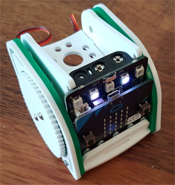
DRIVE LIGHTING AND DIRECTION INDICATORS |
Now you can combine your knowledge and realize some interesting robot applications. Suggestions:
|
A ROBOT REMOTE CONTROL |
Use a second micro:bit to control the robot remotely as follows:
Refer to chapter 7. Bluetooth, to learn how to program the communication between the remote control and the robot.
|