| TigerJython4Kids | robotics |
Warning: Undefined array key 0 in /var/www/html/engl/navigation.inc.php on line 32
Warning: Trying to access array offset on value of type null in /var/www/html/engl/navigation.inc.php on line 32
Getting started Python Crash Course LED Display Accelerometer Buttons Sound Compass Sensor Bluetooth Moving Robots Alarm Systems Workheets Worksheet 1 Worksheet 2 Worksheet 3 Worksheet 4 Worksheet 5 Appendix: Digital Display Documentation mbRobot and IoT NEW!
| Deutsch English |
8. MOVING ROBOT
![]()
YOU LEARN HERE... |
how to construct and program a moving robot. |
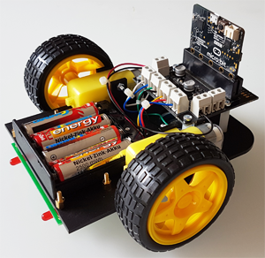
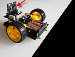
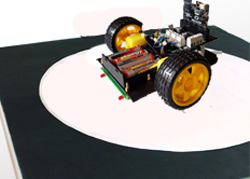
ROBOT "BUGGY" |
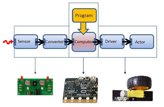
The following block diagram of a "autonomous machine" is very general. You may easily recognize the components on your buggy robot.
Since the micro:bit is part of the machine, it is also called an "embedded system". |
EXAMPLES |
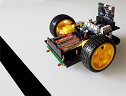
Before you tackle a more sophisticated problem, you should always perform a few tests to verify the proper functioning of each component individually. 1. Tests with the left and right motor
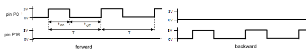
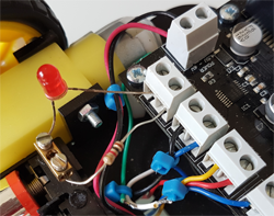
This type of a signal is called pulse width modulation (PWM). You generate a PWM signal at P0 with the command: pin0.write_analog(duty), where duty is a number between 0 and 1023 that determines how long is the ton time with respect to the full period T. The following program makes the left motor first rotate in one direction for 2000 milliseconds with a moderate speed and then in reverse direction for the same time with lower speed. To power the motors, do not forget to turn on the small switch on the bottom of the buggy chassis. The same switch may also serve to switch the motors off at any time. Program: from microbit import * pin0.write_analog(200) sleep(2000) pin0.write_analog(0) pin16.write_analog(100) sleep(2000) pin16.write_analog(0) Perform the same test with the right motor using pins 12 and 8. 2. Tests with the light sensors
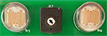
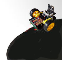
In addition, if the buggy is on a dark surface, the two red LEDs will light up. The left sensor is connected to P1, the right to P2. Your program "polls" the voltage at these terminals and writes out the values in the console window. Program: from microbit import * while True: left = pin1.read_analog() right = pin2.read_analog() print("L: " + str(left) + " - R: " + str(right)) sleep(500)
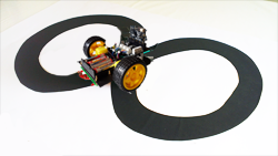
3. Controlling robots
Program: from microbit import * while not button_a.was_pressed(): sleep(10) pin0.write_analog(150) pin12.write_analog(150) sleep(2000) pin12.write_analog(0) sleep(2000) pin12.write_analog(150) while True: left = pin1.read_analog() print(left) if left > 100: pin0.write_analog(0) pin12.write_analog(0) sleep(10)
4. Use commands from the module mbutils
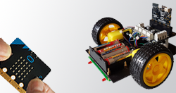
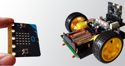
Program: from microbit import * from mbutils import * display.show(Image.YES) while not button_a.was_pressed(): sleep(10) buggy_setSpeed(15) buggy_forward() while not button_b.was_pressed(): if isDark(ldrL) and not isDark(ldrR): buggy_forward() elif isDark(ldrL) and isDark(ldrR): buggy_rightArc(0.6) elif not isDark(ldrL) and not isDark(ldrR): buggy_leftArc(0.6) sleep(10) buggy_stop() display.show(Image.NO) 5. Remote control with a second micro:bit
The program for the buggy: Program: from microbit import * from mbutils import * import radio radio.on() display.show(Image.YES) buggy_setSpeed(20) while True: rec = radio.receive() if rec == "FORWARD": buggy_forward() elif rec == "LEFT": buggy_leftArc(0.6) elif rec == "RIGHT": buggy_rightArc(0.6) elif rec == "STOP": buggy_stop() sleep(10) The program for the control: Program: import radio from microbit import * radio.on() display.show(Image.YES) state = "STOP" oldState = "" while True: if button_a.is_pressed() and button_b.is_pressed(): state = "FORWARD" elif button_a.is_pressed(): state = "LEFT" elif button_b.is_pressed(): state = "RIGHT" else: state = "STOP" if oldState != state: radio.send(state) oldState = state sleep(10) The remote control program is a typical example of state programming. Since the buttons are checked every 10 milliseconds in an endless while loop, you have to make sure that a message is sent only if the state changes (oldState! = state). Otherwise, a superfluous command is sent every 10 ms, unnecessarily burdening the system. |

MEMO |
| In order to put a complex system into operation, you should test individual components and then assemble them all together. . |
EXERCISES |
|
Technical information:
The micro: bit was developed by the BBC to inspire British students to program. One million seventh-graders in the UK were equipped with this device.The board costs about 20 Fr.
Where to Buy